This article will provide you with basic network information.
Hardware
We will discuss what different type of networking equipment you might run into and explain what the differences are.
HUB
A HUB is essentially just a box with wires interconnected inside. Everything that is received on one port is transmitted on all other ports. It can’t change the traffic that is running through or manage traffic. It is not frequently used in network setups today as it is slow and creates a lot of issues such as collisions. Hubs operate on layer 2. This means that devices on different subnets cannot communicate with each other through a HUB. A HUB will allow Broadcast packages to be sent to all devices on a network.
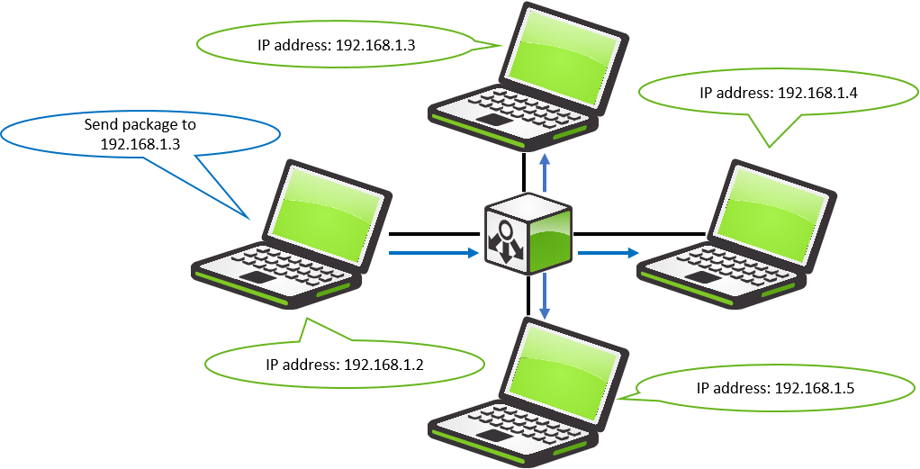
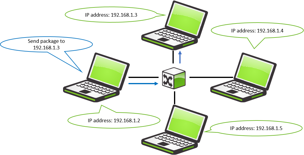
Switch
A Switch acts a lot like a hub where devices that that are connected to it can communicate with each other, but in addition to this, a Switch makes sure that communication is only being sent to the device that needs it, and makes sure that no packages collide. A Switch like a HUB also operates on layer 2, and has the same restraints as the HUB. A Switch will allow Broadcast packages to be sent to all devices on a network.
Router
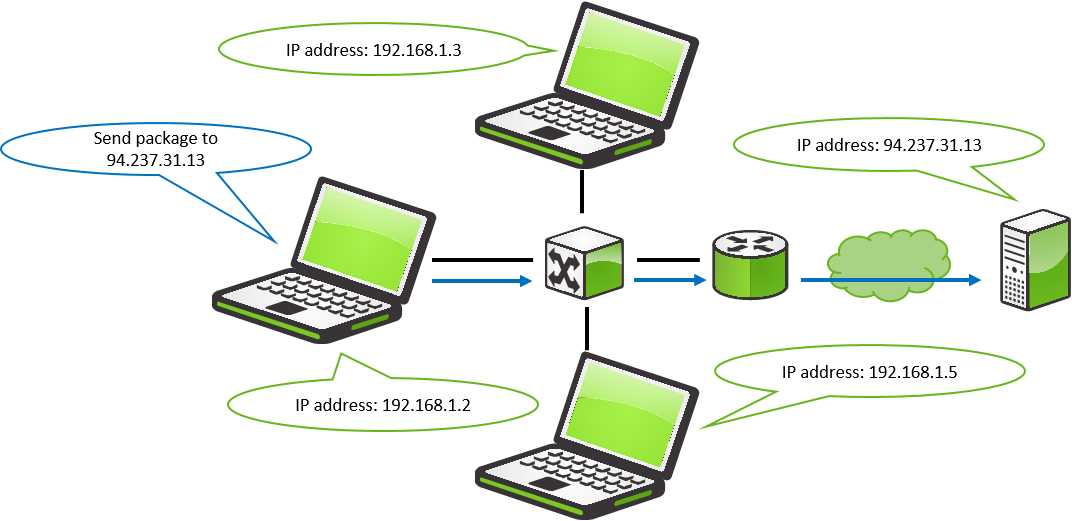
A Router is a device that can establish communication between different networks. This is most often used to make sure that devices that are present on a local network can access devices on the internet, though this can also be used in companies to separate their networks from each other. A router is very different from a Switch or a HUB as it operates on layer 3. A Router will not allow broadcast packages to be sent on the remote network.
Private and public IP addresses.
IP addresses are addresses that are assigned to devices in order for them to communicate with each other. There are some ranges of IP addresses that are assigned to specialised uses, and some that are only used on private and public networks.
Private IP address.
A private IP address is the address space allocated by InterNIC to allow organisations to create their own private network. There are three IP blocks (1 class A, 1 class B and 1 class C) reserved for private use. The computers, tablets and smartphones sitting behind your home, and the personal computers within an organisation are usually assigned private IP addresses. A network printer residing in your home is assigned a private address so that only your family can print to your local printer.
When a computer is assigned a private IP address, the local devices see this computer via its private IP address. However, the devices residing outside of your local network cannot directly communicate via the private IP address but uses your router's public IP address to communicate. To allow direct access to a local device that is assigned a private IP address, a Network Address Translator (NAT) should be used.
| Class | Starting IP Address | Ending IP Address | # of Hosts |
|---|---|---|---|
| A | 10.0.0.0 | 10.255.255.255 | 16,777,216 |
| B | 172.16.0.0 | 172.31.255.255 | 1,048,576 |
| C | 192.168.0.0 | 192.168.255.255 | 65,536 |
Public IP address.
A public IP address is an address that is assigned to a computing device to allow direct access over the Internet. A web server, email server and any server device directly accessible from the Internet are candidates for a public IP address. A public IP address is globally unique, and can only be assigned to a unique device.
Standard ports.
All a SiteManager needs to connect to the GateManager server is an outgoing TCP connection on port 80,443 or 11444. It is however recommended that both port 80 and 443 are open to the GateManager Server.
The OSI model
The OSI model is a representation of the different “layers” that networking has. It is used to describe what’s going on when devices are interacting and how traffic is being packaged on the way to its destination. When a packet is sent from PC1 to PC2 the packet is first packaged one by one by each layer until it has been sent over the physical connection to PC2. When PC2 has received the package it will open up the package on each layer, making sure that it is the intended destination for this package in each layer.
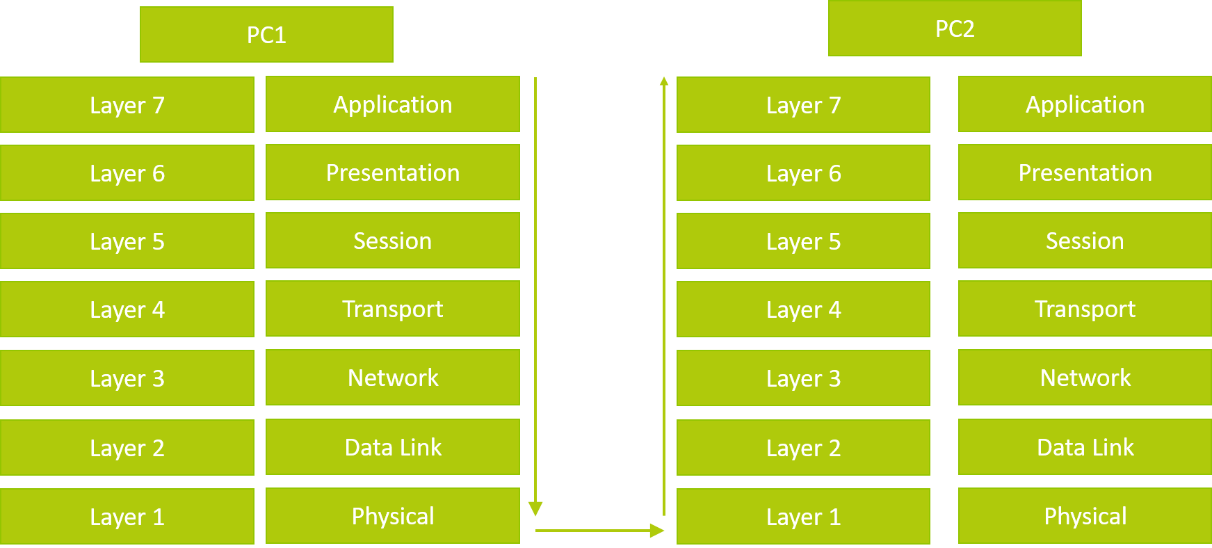
Layer 7: The Application Layer.
This layer represents the visuals that you are working with, this could be anything from our GateManager's interface, to Internet radio stations.
Layer 6-5: The Presentation and Session.
These layers are handled by the operation system, and network drivers to send the data correctly through the OSI stack.
Layer 4: The Transport Layer.
This Layer is responsible for maintaining protocol communication. (Handles the overhead packets in protocols such as TCP, UDP and more.) These are packets like segmentation, acknowledgement and multiplexing.
Layer 3: The Network Layer.
This layer is the one responsible for managing higher-level communication like IP addresses, routing and Traffic Control. This is the layer most agents in a SiteManager operates on, as this traffic can be routed over the internet.
Layer 2: The Data Link Layer.
This layer is responsible for managing the physical addresses that are being used to communicate locally with devices. (MAC address) This also means that you cannot communicate with devices on other networks, as they are separated by routers. This is only used in very few agents on a SiteManager. (Used in the Forwarding, Scada and Layer 2 agent.)
Layer 1: The Physical Layer.
This is the physical media that is transmitting the connection from device to device.
TCP, UDP and ICMP what’s the difference?
In this section, we will look at the most popular protocols that are being used to communicate between devices on a network.
What is a protocol?
The protocol is used to package a packet so it will be received by the receiver in the most optimal way. Some protocols will not accept any errors in the communication where others will accept some loss, it all depends on the need for the transmission.
TCP
TCP (Transmission Control Protocol) is used when you need to make sure that the product that is being sent over the internet arrives intact. This is handled by the protocol ensuring the communication can be established to the end device before starting the data transmission. TCP also awaits an acknowledgement of receipt from the end device. This is done with every package and ensures that 100% of the data has been received.
This is great for when you need to make sure what’s sent is the same as what is received, for example, if you download Firmware, we need to make sure that the whole package has been received on your computer.
UDP
UDP (User Datagram Protocol) is mostly used when you are more interested in the speed of the transfer of the data, and not as much in the integrity. You see it most often when you are watching a video on the internet, or speaking to people using VOIP. If, in these cases, you are missing some packets, or receive them in the wrong order, then this will not be disastrous. As opposed to a TCP package we do not look for any acknowledgement packages, UDP is more interested in the number of packages that can be sent over the connection as quickly as possible.
ICMP
ICMP (Internet Control Message Protocol) is used by appliances to send information to other devices. This can be anything from error messages to responses about services that are unavailable. ICMP is not available to end-users as its main purpose is to enable communication between devices on a network. The main exception from this is that some diagnostics tools like PING and Traceroute rely on this protocol.
NAT/PAT
This section will give you a better understanding of what Natting is, and how it’s important for communication between devices.
NAT
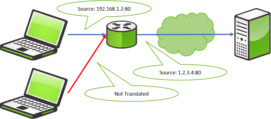
NAT (Network Address Translation) is the practice where a device on one side of a Firewall is translated to another address on the other side. This is a way you can make sure that devices on your local network don't get shown to the outside world.
In this example, you have a device with an internal IP address of 192.168.1.2 and an external IP address of 1.2.3.4. When your computer tries to communicate with a device present on the internet its address will be translated from 192.168.1.2 to 1.2.3.4 by your router. This way we can make sure that the private IP address 192.168.1.2 stays on the local network, and only the public address 1.2.3.4 is being shown on the internet.
Nowadays NAT is not used that often as this is a one-to-one conversion. If you have multiple computers on a local network, then only one of them would be able to access the internet at the time through the router.
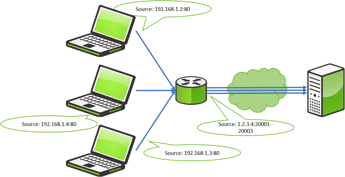
PAT
PAT (Port Address Translation) is often referred to as NAT. PAT Is used to gain the same result as NAT but improves on it by allowing multiple internal devices to communicate through a single IP address. This is accomplished by binding each outgoing connection to a single port. So, if we are in a network with 30 computers, and they all want to access 94.237.31.13 at the same time then they would be able to do this. Each connection to 94.237.31.13 would be sent with the same address (1.2.3.4) but in this case, each connection would get a unique port assigned to the from address. (1.2.3.4:20000 1.2.3.4:20000 and so on.) This way we would be able to figure out who should receive each package that is sent back from the webserver.
DNS
DNS (Domain Naming System) is the library that allows us to translate addresses that we can read and remember as humans into addresses that computers can understand.
Where are DNS servers?
When it comes to DNS servers, these are the ones that you have locally on your network, which can either be some that have been installed intentionally or as part of some networking equipment that your ISP has sent.
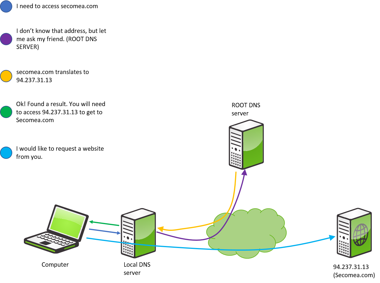
How DNS works.
When you try to access a website from your computer you would use a string like “secomea.com”. The issue with this is that your computer does not know where to send packages, when all it has is a string. So, it asks your DNS server “Do you know what secomea.com translates to?”. If your DNS server knows what secomea.com translates to then it will deliver the result to your computer: “secomea.com translates to 94.237.31.13”. When your computer has received this information, it will open its communication to 94.237.31.13.
If, however, your DNS server does not know the result of secomea.com then it would have to forward the request to the internet ROOT DNS servers. These servers will then be responsible for figuring out what IP address secomea.com refers to and sending the result. And send the result back to your DNS server, which will send the information to your computer.
Broadcast and Unicast.
In this section we will go into detail about what the different communication types are. These are concepts that different layers utilise to communicate in a specific way to end devices.
Broadcast
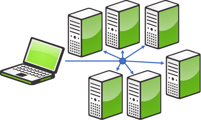
Broadcast is used to communicate with all devices on a network, mostly on layer 2 (ARP or DHCP being an example) but can also be used on layer 3 in some cases.
This feature is great if you need to find a specific device’s IP address and you don’t know who it belongs to. Sending out a broadcast will ask everyone on the network who has a specific IP address and only the one that has that IP address will respond.
Broadcast packages are stopped by Routers/Firewalls. This ensures that they can only be sent on an internal network. Therefore, you cannot broadcast a search for a device through LinkManager without using a Layer 2 agent.
Unicast
Most communication made to other devices from your computer uses Unicast. When you access a device on the internet or access a local device like a printer, then you are using Unicast. This communication is one to one. Unicast is used both on layer 2 and 3. When you send a package to an IP address the communication will be encapsulated in a Layer 2 package.
Unicast packages are not stopped by Routers/Firewalls since this is the main way your computer communicates with devices not located on the local network.
DHCP
DHCP (Dynamic Host Configuration Protocol) is a way of dynamically and automatic assigning IP addresses to devices on a physical network. It’s used in almost every network to make sure that computers do not need any manual configuration to connect to local devices or gain access to the internet. In some special cases, static IP addresses may be desirable over DHCP.
How does DHCP work?
DHCP works on layer 2 in the OSI model. This means that when a device needs an IP address, it can only request one on the same network that it's present on.
The whole DHCP process is called DORA. This stands for:
- Discover – The device that needs an IP Address sends out a Layer 2 Broadcast packet to find a DHCP server.
- Offer – A DHCP server responds with an offer for an IP address that is available.
- Request – The device then sends a packet to the DHCP server requesting the IP address offered.
- Acknowledge – The DHCP server replies with a message telling the device that it’s okay to use the requested IP address.
What happens if no DHCP server is available?
This is different from device to device. In most cases, your device will receive an APIPA (Automatic Private IP Addressing) address. This is a random IP address that your device will assign to its own network card. This IP address is in the 169.254.x.x network. Getting this APIPA Address does not mean that you will be able to use your device in an intended way, as it is an automatic function that activates if your network is experiencing issues.